| Continuing on part 2 of my quest for a nice NA motor that's suited for roadracing, I decided to go with an Integra Type R (ITR) cylinder head swap. Thankfully, I got a great deal on the parts from a friend who had the new parts lying in his garage for ages. |
| Putting the B18C5 (ITR) head onto a B18C1 block is a completely bolt-on process.
The parts required for the swap are as follows:
The new head would reduce compression somewhat due to the larger combustion chamber volume. I opted to remedy this by changing out the pistons to US ITR pistons. And to get a little bit more compression I decided to make a thin head gasket from the stock gasket. The process of the swap is quite straightforward and I'll outline some key points to watch out for along the way. Starting OffAssuming the vehicle is securely on jack stands, start off by draining all the coolant and motor oil from the motor. While the motor oil is draining, undo the valve cover and remove it. While you're there, also remove the entire distributor.Loosen the cam pulley bolts a little so that you can remove the cams
later. Next, remove the camshaft plates and holders. Loosen the outer bolts
first and then work towards the middle. The cams can be easily removed
now. Set them aside if you are going to reuse them (I reused my CTR cams).
|
Click on the pictures to see an enlarged view.
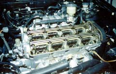
Figure 1 Valve cover and distributor removed 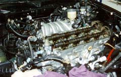
Figure 2 Camshaft plates and caps removed |
Intake manifoldThe intake manifold is next. Go around the intake manifold and disconnect every hose that's connected to the intake manifold. Take note of where each one goes.To make life easier, I also removed the throttle body from the intake manifold, giving more room to work. Next, start loosening the bolts that hold the intake manifold in place. Once all the bolts are off the manifold can be removed. Proceed further by undoing all the exhaust manifold nuts and remove
the exhaust header.
|
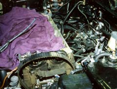
Figure 3 Intake manifold is removed |
Removing the headYou're almost ready to remove the head. First check that that all sensors on the head have been unplugged. Undo the head bolts a little at a time, starting from the outer bolts and working your way to the center bolts. Loosen the bolts evenly so that the cylinder head does not warp.Once all the bolts are free, use a magnet to pull the bolts out of the bolt holes. The head is ready to come off. With one swift move, lift the head straight up and away from the block.
Be careful of oil dripping out from under the head.
|
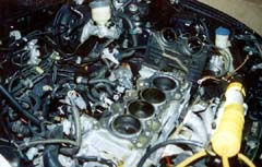
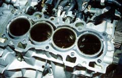
Figure 4 Off with the head! |
Removing pistonsThe next step in the process was to change out the pistons. Assuming the oil pan has been completely drained, proceed to undo the oil pan bolts and remove the oil pan. After removing the oil pan you have to undo the oil pickup, followed by the windage tray.Turn the crank such that the pistons are away from the top of the deck. You will notice a brown ridge caused by carbon deposits. Clean it off with some fine grit steel wool and brake fluid. The connecting rod nuts should be accessible from the bottom.Turn the crank to give yourself access to the bolts if necessary. Loosen the nuts and carefully remove the bearing caps and bearings one by one. Set them aside so you know which came from which cylinder. The pistons and rods can now be pushed pretty easily from underneath the block and should pop out from above. Do this carefully as you don't want to nick the crank journals. Mark each connecting rod as it comes out so as to be able to tell which belongs to which cylinder. The block was in excellent shape for a 60-70k mile motor. The factory
honing marks were still on the cylinder walls and everything was within
brand new factory specs.
|
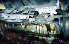
Figure 5 Bottom of the block, oil pan and pickup removed. What you see is the windage tray |
The little thingsSince everything else was coming out of the motor and I had a motor that was close to 70K miles, I felt that it was a good time to replace everything, including the timing belt and water pump.Locking the crank with a home made crank lock, the crank pulley bolt was removed to gain access to the bottom half of the timing belt cover. The old water pump was then removed and the entire internal housing
of the water pump was cleaned with (you guessed it) steel wool.
|
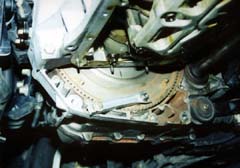
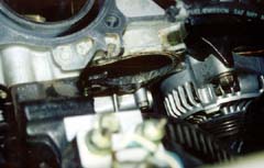
Figure 7 Locking the crank to remove the crank pulley bolt |
Replacing pistonsTake your new pistons and old rod/pistons assembly to a local machine shop. Have the machine shop press the pins out from the old pistons and install the new pistons on the rods.The new pistons are ready to go in. First arrange the new piston rings pointing 45 degrees or so to the intake side. Remember to stagger them. The oil control rings should be facing the exhaust side, also staggered. Refer to the service manual if you are unsure about the ring placements. Oil the pistons and cylinders liberally before proceeding. Next, compress the rings with a ring compressor and carefully tap the pistons into their respective cylinders one by one, taking care not to nick the crank journal. After making sure the big end bearing is seated right on the con rod, reinstall the big end bearing cap. The bearing cap has to be torqued down in 2 stages, the first stage is 22Nm followed by a final tightening to 44Nm. Finally replace the windage tray, oil pickup and then the oil pan.
You should be done at the bottom now.
|
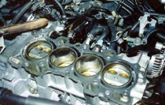
Figure 9 New ITR pistons are installed in the block |
The fun stuffYes, the new cylinder head is ready to be reinstalled. First, put the 2 dowel pins onto the corners of the engine block. If you don't have any dowel pins, carefully pull them off the bottom of your old cylinder head.Now grab the head gasket. You will notice that it comes in 3 layers. I opted to only use one of the three layers -- the bottom one. Be aware that you have to have an almost perfectly flat deck to do this (yes, I checked). In addition it takes very careful torquing down of the cylinder head to get a good seal with a thin head gasket. Place the head gasket onto the block, making sure that it is the right way up and that it fits the dowels properly. Next lower the new head carefully onto the block so that the holes line up with the dowel pins and press it firmly down. Place all the head bolts in and tighten them just enough that they just
stop, Using a torque wrench, torque down the head evenly from the 2 middle
bolts outwards. Tighten all the bolts in 3-4 torque increments, with the
final torque set to 64Nm. The proper proceedure is also in your Helms manual.
|
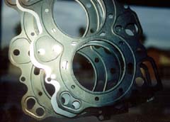
Figure 10 The stock head gasket, in 3 layers.
|
Finishing up the headThe next step is the replacement of the cams and the cam holder assemblies. This is a relatively simple process and is the reverse of the removal. If a new timing belt is to be used, this is the time to put it on. Replace the timing belt cover.I also took this opportunity to replace the stock cam gears with adjustable ones, which will be set on a dyno later. Finally plug in all the sensors (transplant them from the old head) and connect up the heater hoses.
|
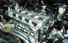
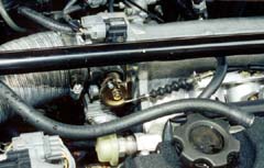
Figure 12 Cams replaced, adjustable cam gears installed |
Intake installationThe ITR intake manifold is relatively easy to install. It bolts up to the head easily and without any problems. Connect any hoses you disconnected earlier.The IAC plug needs to be extended about 6 inches so that it will plug into the IAC on the ITR T/B. The rest of the sensors will plug in nicely. Install the fuel injectors and the fuel rail. Remember to connect the fuel return hose otherwise you'll have a major gas leak when the car is started. The GSR throttle body needs to be modified to work properly. The stock pulley was replaced with a DX pulley and an adapter can be easily fabricated from a strip of aluminum.
|
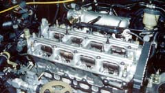
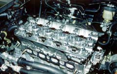
Figure 13 Intake manifold installed |
Finishing upThe last stage of the swap involves doing a valve clearance for all the valves. Instructions for valve clearance can be found on the camshaft install page.With that completed, close up the valve cover and reinstall the distributor. Give everything a once-over, making sure that all hoses and tubes are connected to the correct places. Fill the motor up with oil and coolant and you're ready to start the car! |
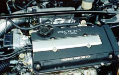
Figure 15 Finally done! |
|
|
|
|
|
|
|
(C) 1996, 1997, 1998, 1999, 2000 HYBRID Comments? Suggestions? Feedback? Send e-mail to: HYBRID editors |